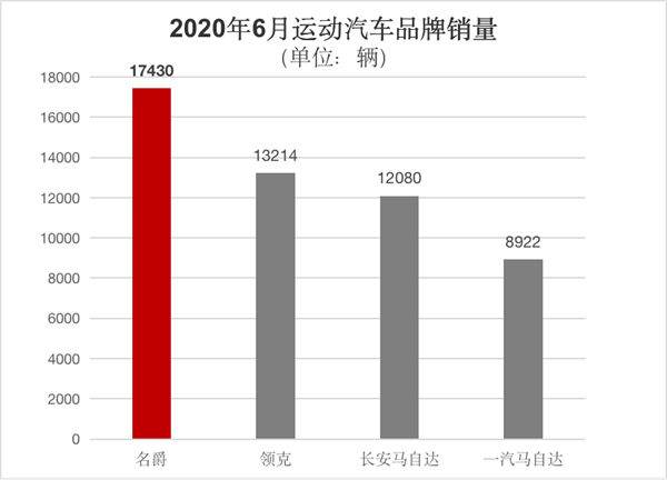

The draft hand-painted pictures cannot be displayed after copying. There are many pictures taken below for you to understand.
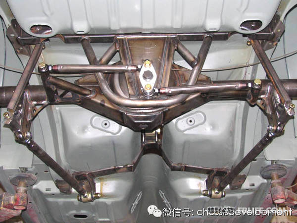
This modification took more than half a year from theoretical design to buying parts to final installation. During the period, I found more than a dozen auto repair shops, but they were unwilling to weld according to my requirements. A few days ago, I happened to meet a repair shop willing to weld, which led to the success. This modification. This post can be used as a reference for friends all over the world who want to modify the vehicle with the whole rear axle into a Watt connecting rod connection structure. This is also the first time that the Internet has the production standard of Watt connecting rod. The following is the vehicle Structural characteristics of the Panhard and Watt links used.
I once drove Yusheng to test drive Everest. On the same section of the road, I passed speed bumps at high speed and cornered at high speed. For the first time, I felt the huge gap caused by different structures. Everest can be more efficient than Yusheng Safe cornering at high speeds, when the Road Shaker and Kai Yusheng pass the speed bump at the same position, the Road Shaker will not swing its tail when passing the speed bump, and it is still very stable after the car jumps and lands. It can accelerate forward, but Yusheng dares to accelerate forward only after slowing down until the rear of the car stops shaking. The rattling of the rear of the car makes people dizzy and guilty, afraid of losing control. From this I began to pay attention to the Watt connecting rod.
I have always wondered in my heart: These three rods are connected together to form a Watt connecting rod? Is it really that simple? So I did a simulation experiment by myself, and after countless model experiments, I finally discovered the secret of the Watt connecting rod. The rod is not simple, so it is found that some Watt connecting rods on sale are unqualified, and it is found that many diagrams of Watt connecting rods on the Internet are incorrect.
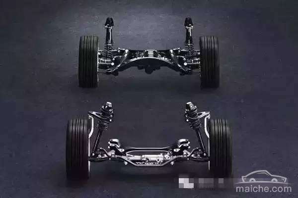
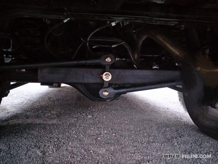
We know that the rear axle is an off-road vehicle with a whole bridge. In order to make the displacement of the carriage and the rear axle up and down movement controllable, a Panhard connecting rod is generally used to connect the axle and the carriage (usually called a thrust rod). Yusheng Prado Cruiser is such a structure. The structure of the Panhard connecting rod is in a circular working state. The center of the circle is the connection point of the axle, and the top of the radius is the compartment. This is its structural feature and its disadvantages.
In the picture below, you can clearly see the activity of this structure. The hand-drawn drawing shows the movement trajectory of the Panhard connecting rod. Our car is moving forward, and no one wants the rear of the car to shake left and right when encountering bumpy roads. , one is dizziness of shaking people, and two is easy to lose control, especially when this happens when turning fast, it is very dangerous. Is there a structure that allows the carriage and axle to only move up and down without shaking left and right? ?The answer is the watt connecting rod and tripod structure (it is the Ozeki knife arm mentioned by the riders, and the chassis of the off-road master is designed in this way). Let’s just talk about the watt connecting rod here!
The structural feature of the Watt connecting rod is to allow the car and the axle to only move up and down in a straight line within a certain range without shaking left and right. The key is this straight line motion, just like the straight line motion of the piston in the cylinder, which is very important for the vehicle Stability is very important during operation. Since the structure of the Watt connecting rod is so good, it does not look complicated. Is it possible to find three bars welded to the car to be the Watt connecting rod? The answer is no. At present There are two structures for the Watt link in the car, one is the Cruz Watt link structure, and the other is the Watt link structure of the Everest. These two structures can keep the car and the axle in a straight line when moving up and down Sports, but each has its own advantages and disadvantages. My analysis is that the Cruze’s Watt link has less damage to the central axis of the Watt link. The Everest’s Watt link structure plays the role of some anti-roll bars.
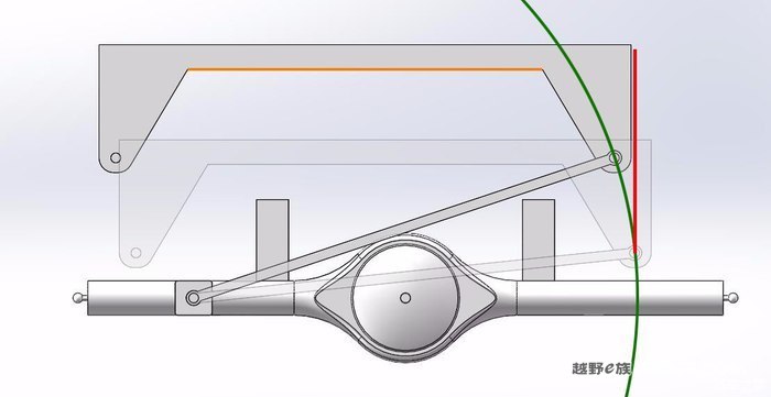
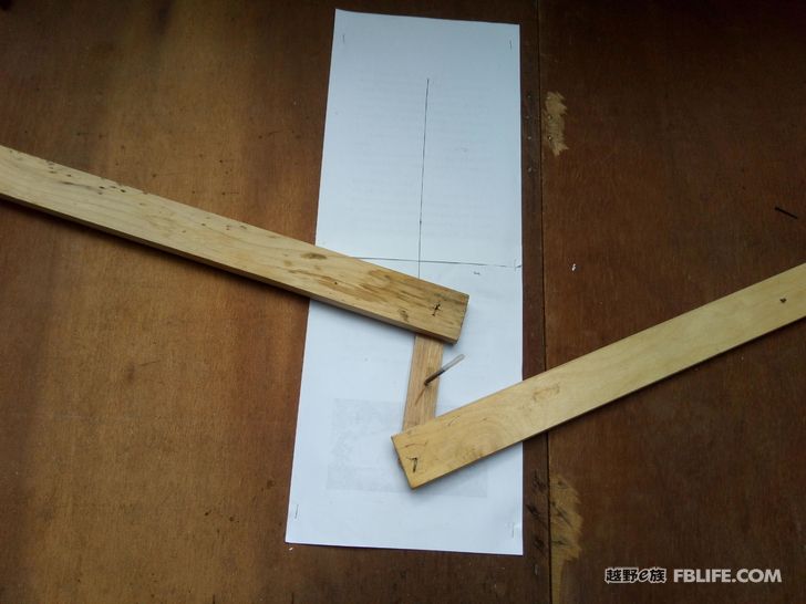
After comprehensive consideration, I refitted Yusheng and chose the structure of the Watt connecting rod of the Everest. Below I draw a basic schematic diagram of a Watt connecting rod. The following is a simplified connection diagram of the Watt connecting rod of the two models actually used. We know that the car The reason for installing the Watt connecting rod is because its center running trajectory is a vertical line, as shown in Figure 1 below, but after countless simulation experiments of the model, I found that the qualified Watt connecting rod is conditional to follow a vertical line. It is not just finding three rods welded together to be called a Watt connecting rod.
This condition is the core principle of making a qualified Watt connecting rod: the various data of the Watt connecting rod must be determined under the three-line parallel principle. After determining the standard data, there are two invariable data and one variable in this set of standard data. Change the data, if you change any of the two unchanging data, the whole set of data must be redone.. Repeat twice: the three-line parallel principle. When designing the data of the Watt connecting rod of the model, the two upper and lower connecting rods must be parallel and parallel to the reference line at the same time. The data formed after reaching the three parallel lines is the only accurate data. Explanation: When the Watt connecting rod moves up and down, There must be a position where the upper and lower connecting rods are in a parallel state. If the Watt connecting rod is required to move vertically with the reference line, then the upper and lower connecting rods must also be parallel to the reference line when they are parallel. This is the “three-line parallel principle” (our vehicle The reference line is the axle). The two constant data under the three-line parallel principle just mentioned refer to the middle distance and the length of the middle swing arm when the upper and lower connecting rods of the Watt connecting rod are parallel (because Once the left and right fixed points of the Watt connecting rod are welded, the horizontal distance and vertical spacing between the two fixed points will remain unchanged.
In addition, the length of the middle swing arm you bought is also the same), a variable data refers to the length of the upper and lower connecting rods (that is, the length of the left and right connecting rods determined under the principle of three parallel lines, but because the middle shaft assembly According to the actual needs, fine-tune the left and right connecting rods, one can be longer and the other can be shorter. One centimeter will be increased on one side, and the other will be decreased by one centimeter. This adjustment will not affect the vertical line of the hole in the middle swing arm. The characteristics only affect the length of the stroke of the middle hole of the middle swing arm along the vertical line. The longer the upper and lower connecting rods in theory, the longer the length of the vertical line of the middle hole of the middle swing arm.). Below I will show you the standard Watt connecting rod with pictures Design data pattern. The above figure 2 is the data and installation diagram of the qualified Watt connecting rod for the car. During the installation, because the middle swing arm of the Watt connecting rod can move up and down, we can see that the Watt connecting rod is actually a standard Watt connecting rod deformation.
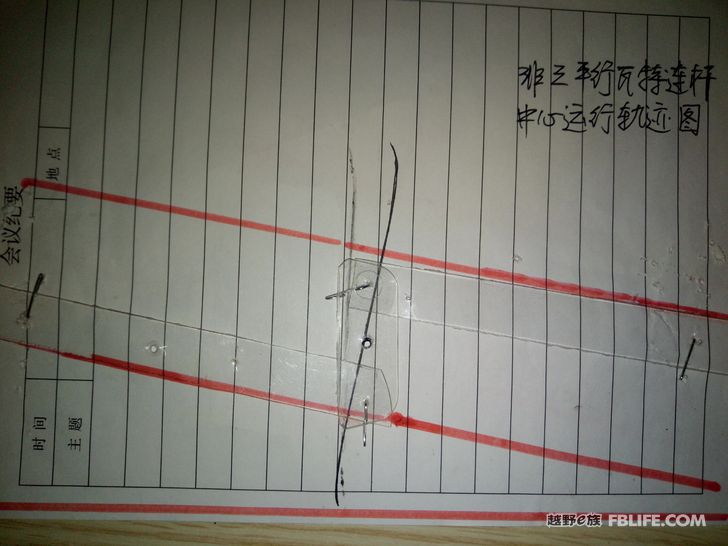
The figure below is a schematic diagram of the running track of the carriage and axle of the unqualified Watt connecting rod. The unqualified Watt connecting rod is oblique and straight, and it will have two problems: First, its carriage and axle will move simultaneously when they move up and down. The left and right displacements follow a slanted line, which will increase the wear on the middle bolt shaft of the Watt connecting rod. Second, when the vehicle goes up and down substantially, the rear of the car will still have the same unstable left and right displacement as the Panhard connecting rod. However, due to the Watt connecting rod When I simulated the model experiment, I found that if the Watt connecting rod is unqualified but the deviation is not too large, although there will be left and right displacement when it moves up and down, the displacement will not be very large. Therefore, the unqualified Watt connecting rod After loading the car, the owner still feels that it will be better than the original Panhard connecting rod. However, if it is unqualified, it is unqualified. Now that everyone knows the three-line parallel principle of Watt’s connecting rod design, anyone can make a qualified one. Watt connecting rod is here..
The running track diagram of the Panhard connecting rod (called thrust rod below) used by Yusheng. The body moves up and down and shifts left and right at the same time. Let me show you the example of Yusheng in the picture below
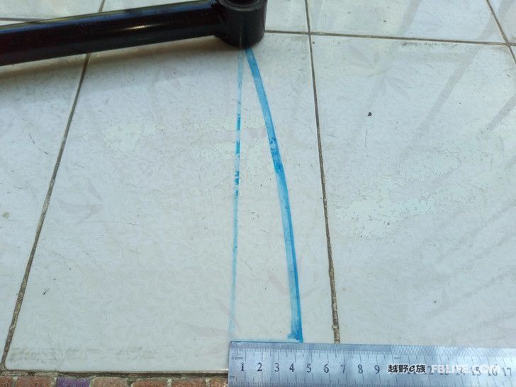
The left and right displacement of Yusheng’s connecting rod is 4 cm after rising 27 cm. This is the instability factor. Not enough. Ordinary people seldom jump so high all of a sudden. Therefore, you need to be gentle when driving this kind of car, and you can’t be arrogant and ups and downs, otherwise you will be thrown into the ditch easily.
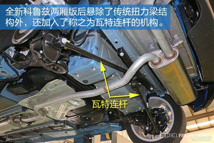
Correct Cruze Watt linkage structure
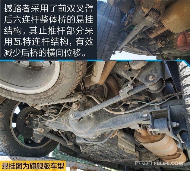
Correct Everest’s Watt linkage
The wrong Watt connecting rod structure on the Internet, its center trajectory is slashed
Unqualified Watt connecting rod structure, its center trajectory is inclined
The center of the wrong Watt linkage structure is slashed.
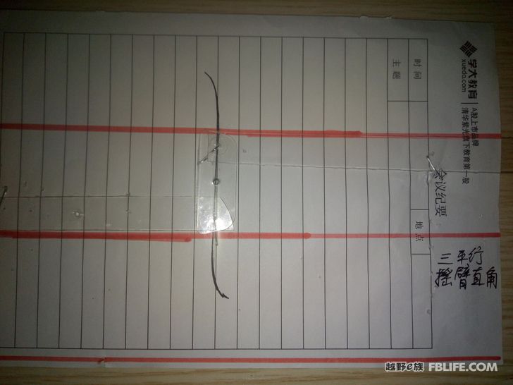
The center of the Watt connecting rod made under the principle of three parallel lines follows a vertical line.
I simulated the central trajectory diagram of the Watt connecting rod which is close to Yusheng’s loading size. This is only a preliminary simulation, and the actual loading requirements are extremely accurate.
Do you see that there is a left and right displacement in the trajectory of the center? It is almost a straight line, which is the guarantee for the stable operation of the vehicle.
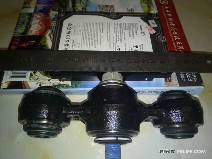
I bought the original Watt connecting rod of the Everest, which is quite expensive and is said to be imported. Friends who want to change the watt connecting rod of Yusheng, please note that the 265 spare tire of Yusheng’s original car takes up too much space, and you must replace it with a 235 spare tire to change this watt connecting rod.
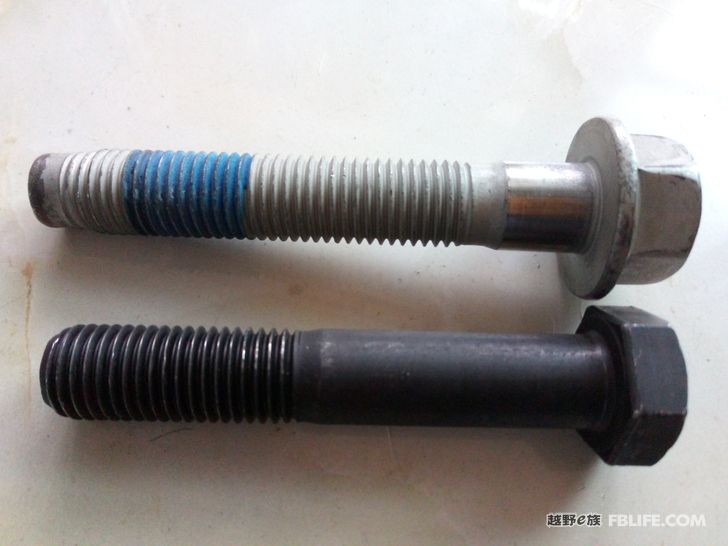
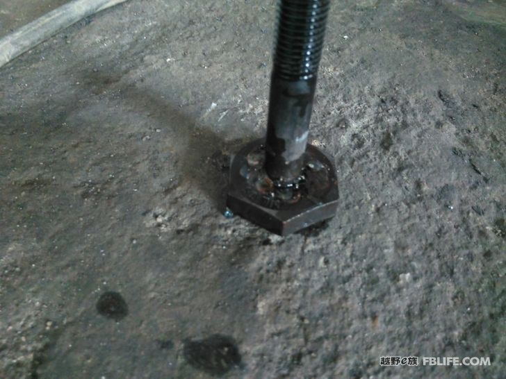
The optical axis of the original screw (silver) is too short, I didn’t use it, I used the black bolts I bought myself
Remove the spare tire, rear balance bar and thrust rod. Drain the oil from the rear axle.
Enlarging the screw base
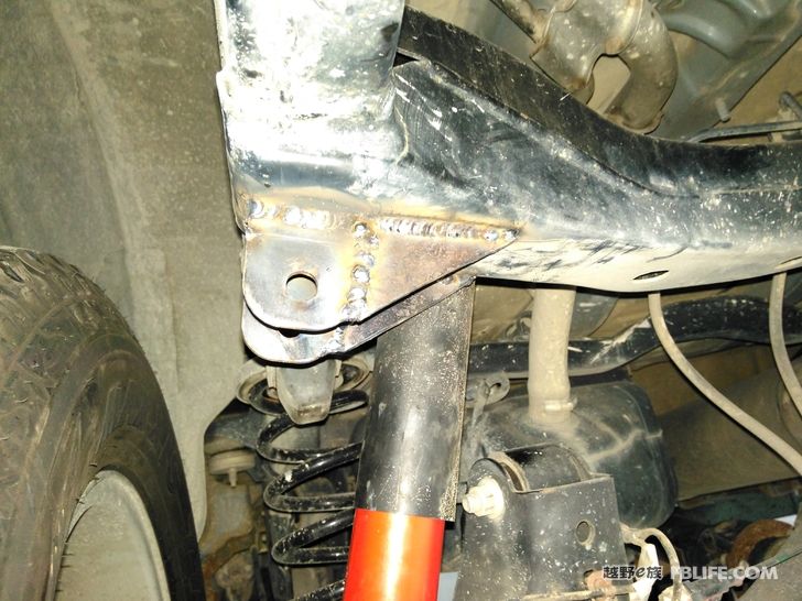
The welding of this fixed base is the most important thing. It must be parallel up and down, horizontally, left and right, and the welding must be very firm. It requires a very professional master to do it.
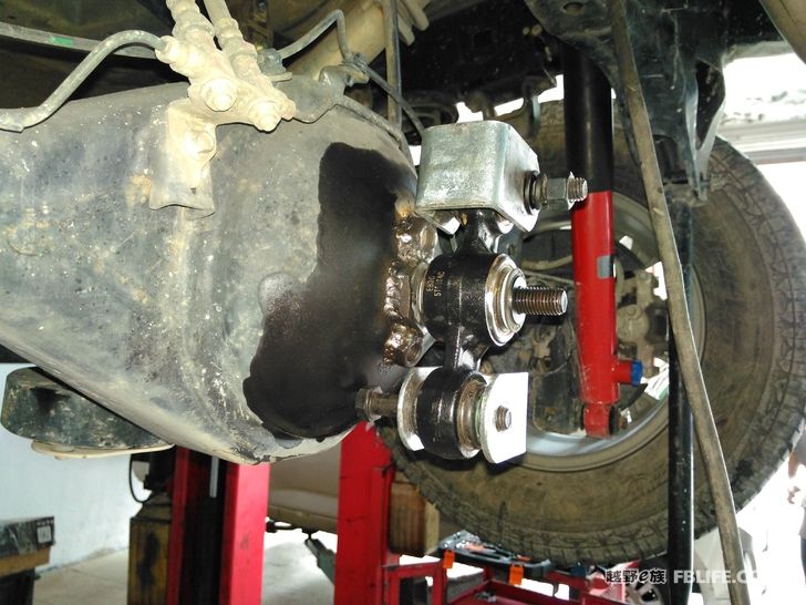
Solder the base on the left. The base on the right is from the original car.
It was originally welded like this, but after the actual loading of the car, it was found that they touched together after the extreme pressure, so it was changed to the following, which actually has no effect, because the data has not changed.
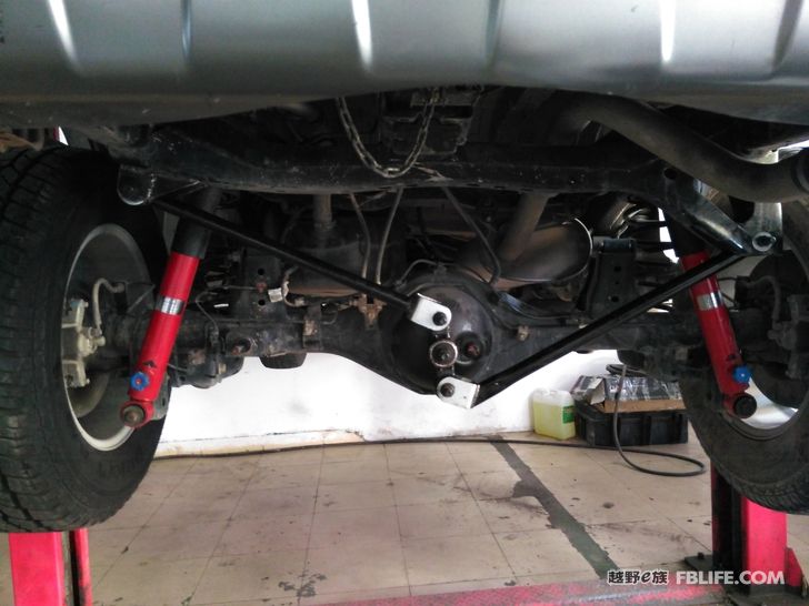
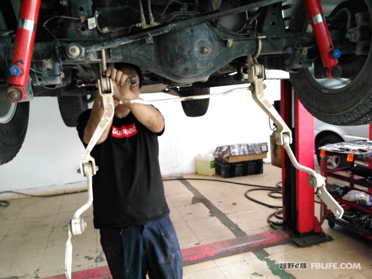
Actual loading diagram. Due to careful research, the length of my left and right connecting rods is now longer than that of the Everest, so the straight line travel of the center track of the rear axle is longer than that of the Everest.
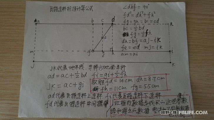
This is the standard formula for calculating watt linkages. Everyone designs according to this, and anyone can make a qualified Watt connecting rod.
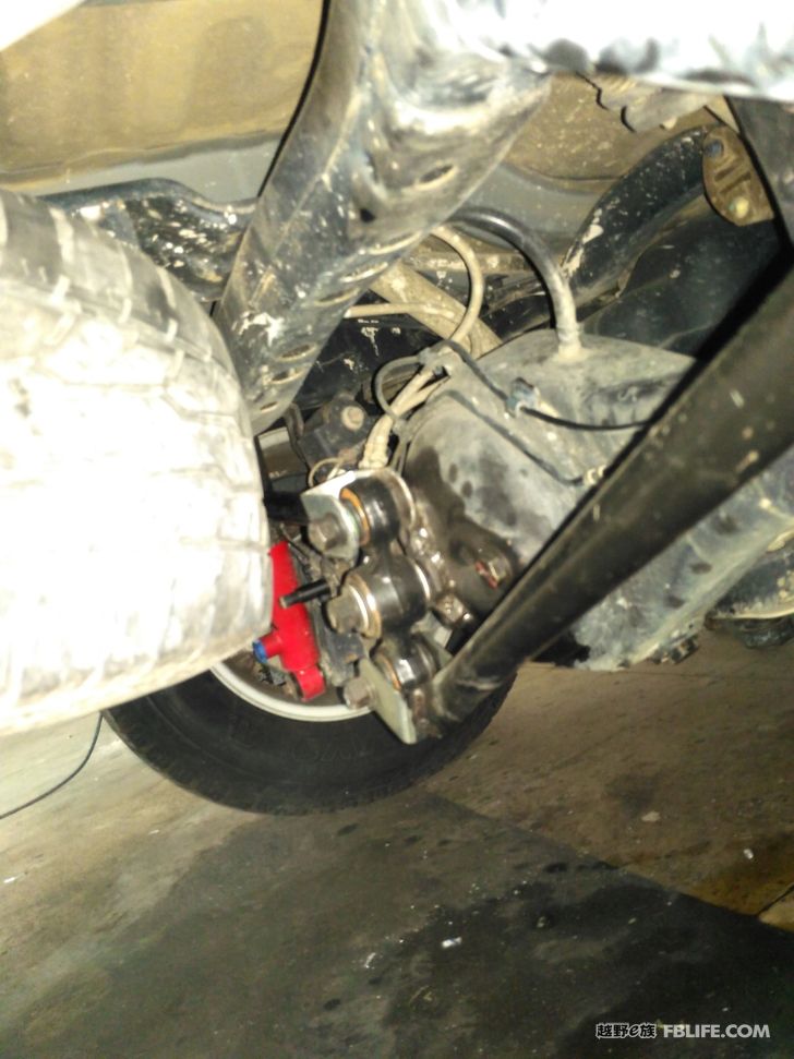
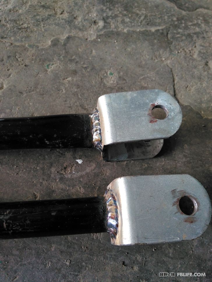
close-up